Parallel To Serial Conversion Simulink Coder
• • • In the majority of the hardware-based activities outlined within these tutorials, we will employ the ArduinoIO Package from the MathWorks for handling the interface between Simulink and our hardware. We use this package because it allows for rather transparent, real-time communication between Simulink and the Arduino Uno (and other models of Arduino board) without delving into the intricacies of serial communication.

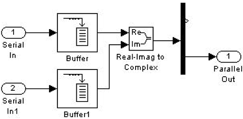
Please help: If there is an integer number source with: M-ary = 2 and Sampling time Ts = 1e-3 (1 ms). I want to make a serial to parallel simulink model with the.
You can download the ArduinoIO Package or from the. Some Arduino boards (for example, the Mega 2560) can be communicated with while an experiment is running using the standard Arduino Hardware Support Package by running Simulink in External Mode. Details on this support package can be found. Note R2014a or higher is needed. The ArduinoIO Package that we will primarily be employing consists of a simple sketch program that runs on the Arduino board and a special blockset for Simulink. The program acts as a server for passing information between the hardware and the host computer running a Simulink model (which employs the specialized blocks).
In these applications, any control logic that we develop in Simulink will run on the host computer. Together, these elements allow us to access Arduino digital inputs and outputs and analog inputs, and read encoders, all from Simulink (or the MATLAB command line). In the case that we wish to create a standalone project that does not need to be connected to the host computer (for example, an autonomous mobile robot), we will then need to deploy our control logic to the Arduino.
We can achieve this using the previously mentioned standard Arduino Hardware Support Package. In this case, the Arduino board won't be running a server program, but will rather be running a program that has been compiled into executable code from the Simulink model we created. Details can be found within the individual activities of the tutorial. Be aware, if you wish to run the Arduino board separate from the host computer, you will need to supply a separate power source for the board, i.e.
A 9-Volt battery. Getting started Once you download and unzip the ArduinoIO package, you can start by taking a look at the included readme file. We will repeat some elements of the instructions here, but the readme file includes more detail. Connecting to the Arduino Board The first thing we need to do is to get our Arduino board up and running. Step-by-step instructions on how to connect the board to the host computer and how to download the driver for the board can be found. This link also describes the Arduino development environment (IDE) and how to upload a test program to your board. The Arduino IDE consists of an editor that allows you to write programs (called sketches) and then build, compile, and upload executable code to your board.
In general, we will only use the IDE to upload our server program. Uploading the Server Program The 'server' program will run on the Arduino board in parallel with the Simulink model running on the host computer. The program runs continuously and receives commands from the Simulink model via the serial port. It then executes those commands and, if needed, returns a result.
There are several versions of the program included as part of the IO package. We will, in particular, employ the sketch adioes.pde. This sketch performs analog and digital I/O (the 'adio'), reads quadrature encoders (the 'e'), and can interface with motors via a shield (the 's'). We will not employ a motor shield in the activities of this tutorial. Note that.pde is an older file extension and Arduino now uses the.ino extension. The following instructions are needed to upload the adioes.pde file into the Arduino board's flash memory. As long as no other file is uploaded later, this step does not need to be repeated and the IO package can be used as soon as the board is connected to the host computer.
From the Arduino IDE toolbar menu, select File >Open and locate the file adioes.pde (in the ArduinoIO/pde/adioes folder) and open it. Next connect the Arduino board and make sure that the correct board and serial port are selected in the IDE (check menus Tools/Board: and Tool/Port:), then select File >Upload and wait for the 'Done Uploading' message. At this point the adioes.pde file is uploaded and you can close the IDE, which is not needed any longer for the purposes of this package. Closing the IDE is actually recommended in order to ensure that the serial connection to the Arduino board is not engaged by the IDE when MATLAB needs to use it.
Package Installation Run MATLAB as an administrator (just one time for the purpose of installing the package) by right-clicking on the MATLAB icon and selecting Run as Administrator. This will allow the updated path to be saved. Xforce Keygen 2016 Torrent. Then set the current MATLAB directory to the location of the file install_arduino.m (in the ArduinoIO/ folder).